Introduction to Spanning Tree Protocol
Spanning Tree Protocol (STP) is a Layer 2 network protocol designed to prevent switching loops in Ethernet networks. STP ensures a loop-free topology by blocking redundant paths while still allowing backup links for redundancy.
In modern enterprise networks, switches are interconnected using multiple links to improve reliability and fault tolerance. However, redundant connections can create broadcast storms, MAC address instability, and multiple frame copies. STP solves these problems automatically.
Spanning Tree Protocol was developed by IEEE and standardized as IEEE 802.1D.
A Brief History of STP
In the 1980s, engineers started connecting network switches with extra backup cables for redundant links. However, this created a data loop problem. As a result of which, data messages would travel around these loops endlessly, causing the switches to overload and crash.
The Spanning Tree Protocol was introduced in 1985 to avoid endless loops by keeping only one link active while the other one remains in an idle condition.
In 1990, STP became the official international standard, known as IEEE 802.1D.
Why STP is So Important
Without STP, a redundant network will collapse within seconds due to three fatal phenomena:
- Broadcast Storms
- Switches do not have a Time-to-Live (TTL) counter in Layer 2 Ethernet frames (unlike routers in Layer 3). If a switch receives a broadcast frame (like an ARP request), it floods it out of every port. In a loop, Switches A and B will endlessly bounce that broadcast back and forth. The traffic multiplies exponentially until the switches run out of CPU and memory, completely freezing the network.
- MAC Database Instability
- Switches learn where devices are by looking at the source MAC address of incoming frames. If a loop exists, the same frame arrives on different ports a millisecond apart. The switch’s MAC address table constantly rewrites itself (“flapping”), causing the switch to drop traffic or send it to the wrong port.
- Multiple Frame Copies
- A destination device might receive multiple copies of the exact same data frame arriving from different paths. This confuses higher-layer protocols (like TCP) and wastes valuable network bandwidth.
How STP Works: Step-by-Step
STP uses specialized packets called BPDUs (Bridge Protocol Data Units) to chat between switches, share information, and elect paths. It builds a loop-free tree topology by following three rigid election steps:
Step 1: Electing One Root Bridge
Every switch has a Bridge ID (BID), which consists of a configurable Priority number and its physical MAC address.
- Bridge Priority (2 bytes) ID value ranges from
0to 65535. The default value on all standard enterprise switches is32768. - MAC Address (6 bytes) is the unique physical burned-in address of the switch hardware.
- The switches exchange BPDUs.
- The switch with the lowest Bridge ID wins the election and becomes the Root Bridge (the master switch of the network).
During bootup, every switch assumes it is the Root Bridge and begins broadcasting BPDUs declaring itself as such. When a switch receives a BPDU with a lower Bridge ID, it yields and begins forwarding the superior BPDU. The switch with the absolute lowest Bridge ID wins the election.
💡 Note: Because the default priority is identical across all devices (
32768), the oldest switch with the lowest numerical MAC address would naturally win the election. To prevent a weak edge switch from accidentally becoming the center of your network architecture, network engineers manually configure the core switches with a lower priority value (e.g.,4096or24576).
Step 2: Electing Root Ports (RP)
- Once the Root Bridge is elected, every remaining non-root switch must select exactly one physical port to serve as its Root Port.
- The Root Port is the interface that offers the lowest total Root Path Cost back to the Root Bridge.
- Port cost is determined by speed (e.g., a 1 Gbps link has a lower cost/higher preference than a 100 Mbps link).
Path cost is inversely proportional to the speed of the interface link. The higher the bandwidth, the lower the STP cost:
| Link Speed | Old 802.1D Cost Standard | Modern 802.1W RSTP Cost Standard |
| 10 Mbps | 100 | 2,000,000 |
| 100 Mbps | 19 | 200,000 |
| 1 Gbps | 4 | 20,000 |
| 10 Gbps | 2 | 2,000 |
Step 3: Electing Designated Ports (DP) and Blocking the Rest
After switches identify their paths back to the master node, they must evaluate every remaining physical cable segment connecting them to each other.
- On each segment, the switch port that advertises the lowest cumulative cost back to the Root Bridge is elected as the Designated Port.
- All ports on the Root Bridge itself automatically default to Designated Ports because their cost to reach themselves is zero.
- Any port left over that has not been chosen as a Root Port or a Designated Port represents a redundant looping path.
- It is designated as a Non-Designated Port and placed into a Blocking State. Traffic is dropped on this port, successfully breaking the loop.
The 5 STP Port States
To prevent a switch port from prematurely forwarding data frames before the spanning tree algorithm has finished mapping out the network topology, traditional 802.1D STP forces interfaces through a sequence of five progressive states:
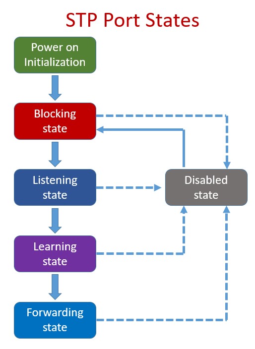
- Blocking: The port is completely locked down to prevent user data loops. It discards all incoming data frames and cannot learn MAC addresses. However, it does listen for incoming BPDUs to stay aware of topology changes.
- Listening (15 seconds): The port transitions out of blocking if a link failure occurs. It processes BPDUs to determine its new role in the topology but does not pass user traffic or populate the MAC table yet.
- Learning (15 seconds): The port still blocks user traffic but begins inspecting the source MAC addresses of passing control frames to actively build its CAM table, preparing to forward data efficiently.
- Forwarding: The port becomes fully operational. It sends and receives BPDUs, updates MAC tables, and passes production user data frames seamlessly.
- Disabled: The interface has been manually shut down via software administration (
shutdown), removing it entirely from the spanning tree topology.
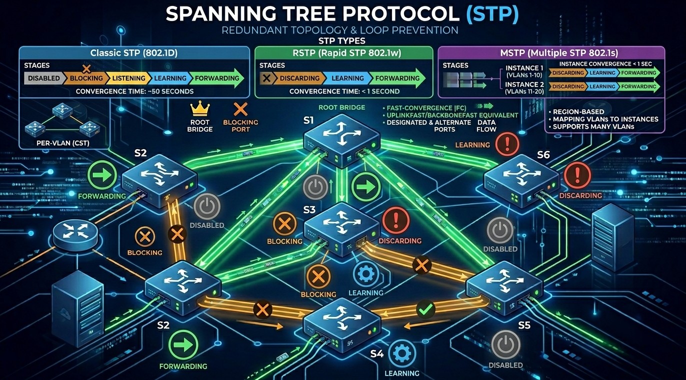
Types of Spanning Tree Protocol
Over the years, Spanning Tree Protocol (STP) has evolved to keep up with faster network speeds and complex setups using Virtual LANs (VLANs).
Here are the 5 main types of Spanning Tree Protocol you will encounter in networking today, ranging from the oldest version to modern standards.
1. Original STP (IEEE 802.1D)
This is the grandfather of loop prevention, created by Radia Perlman in 1985.
- How it works: It creates one single loop-free path map for the entire network, no matter how many VLANs you have.
- The Downside: It is incredibly slow. If a cable breaks or a switch goes down, it takes 30 to 50 seconds for the network to recover and find a backup path.
2. PVST+ (Per-VLAN Spanning Tree Plus)
It was developed by Cisco to fix a major limitation of the original STP.
- How it works: Instead of one map for the whole network, PVST+ runs a completely separate copy of STP for every single VLAN you create.
- The Benefit: It allows for “load balancing.” For example, you can tell your switches to use Cable A for your Finance VLAN, and Cable B for your HR VLAN.
- The Downside: It still uses the old, slow 30-to-50 second recovery timers.
3. RSTP (Rapid STP / IEEE 802.1W)
As internet speeds grew, waiting 50 seconds for a network to fix itself became unacceptable. RSTP was created to solve the speed problem.
- How it works: It uses an advanced handshaking system between switches to bypass the old, slow waiting timers.
- The Benefit: It is incredibly fast. If a cable fails, RSTP finds a backup path in under 2 seconds.
4. Rapid PVST+
This is a Cisco-proprietary protocol that combines the absolute best features of the previous two types.
- How it works: It takes the lightning-fast speed of RSTP and applies it to a per-VLAN setup.
- Current Status: This is the default, out-of-the-box setting on almost all modern Cisco switches. It gives you 2-second recovery times and excellent flexibility, though it requires more switch CPU power to run.
5. MSTP (Multiple Spanning Tree Protocol / IEEE 802.1S)
In massive data centers or enterprise networks that use hundreds of VLANs, running a separate copy of STP for every single VLAN (like Rapid PVST+) can completely overload the switch’s processor.
- How it works: MSTP groups multiple VLANs together into a few logical “buckets” or instances.
- The Benefit: For example, if you have 500 VLANs, you can group them into just 2 instances. This gives you the speed of RSTP and the load balancing of PVST+, but saves a massive amount of switch CPU performance.
Quick Comparison
| Protocol Name | Standard | Recovery Speed | Best Used For |
| STP | IEEE 802.1D | Slow (30-50 sec) | Legacy networks (rarely used today) |
| PVST+ | Cisco | Slow (30-50 sec) | Older Cisco networks |
| RSTP | IEEE 802.1W | Fast (Under 2 sec) | Standard non-Cisco networks |
| Rapid PVST+ | Cisco | Fast (Under 2 sec) | Modern Cisco networks (Default) |
| MSTP | IEEE 802.1S | Fast (Under 2 sec) | Massive networks & Data Centers |
Conclusion
Spanning Tree Protocol is one of the most important Layer 2 protocols in computer networking. It prevents switching loops, protects the network from broadcast storms, and ensures reliable communication between switches. Understanding STP concepts such as Root Bridge election, port roles, port states, and BPDU operation is essential for network administrators and Cisco certification students.
Modern networks commonly use Rapid Spanning Tree Protocol (RSTP) and Rapid PVST+ for faster convergence and better performance.