In this section, we will discuss yet another important topic “How spanning tree protocol works”. In the earlier section, we learned about the basic concept of spanning tree protocols.
How Spanning Tree Protocol Works
During the process of the spanning tree, STP uses the spanning tree algorithm to make a decision about which switch port will be in a blocking state to prevent loop conditions in the layer 2 network.
Switching Loop
The layer 2 switch has only one broadcast domain. It forwards both broadcasts as well as multicast frames to all the switch ports except the forwarding port. When a switching loop occurs, a disastrous broadcast storm floods the entire network within seconds and the frame is forwarded through the loop endlessly. Consequently, the entire network is blocked.
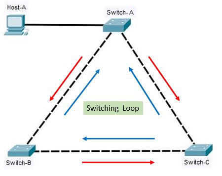
Let us look at the topology shown above. The Host-1 sends out the broadcast frame to the directly connected Switch-A. The Switch-A then forwards the broadcast frame to all the ports having the same VLAN ID including the trunk connected to Switch Switch-C, Switch-B forwards the broadcast to C and Swirch-c also forwards the broadcast to Switch- B. Thereby causing endless network loop issue.
When STP is introduced in the above topology, first it builds the topology of the entire network and identifies the loop in between the switches. In such cases, it disables or blocks the port that is creating a loop. The disabled or blocked port is re-activated, if the active port fails.
STP provides fault tolerance and maintains redundant links to keep on standby if the active link fails.
| However, STP does not support load balancing. Etherchannel is implemented to efficiently use a redundant link to increase the overall bandwidth of the network. |
The process of STP convergence involves mainly three steps.
- Election of the root bridge
- Identification of root port
- Identification of designated port
Step 1: Election of the root bridge
- The very first process in STP convergence operation is to elect a root bridge.
- The root bridge acts as the central reference for the STP topology.
- The switches exchange BPDU frames with the directly connected neighboring switches and participated in the election process to determine which switch has the lowest bridge ID.
- The root bridge is elected on the basis of its bridge ID
- The switch having the lowest bridge ID is considered the root bridge.
- The bridge ID consists of – a 16-bit bridge priority number and a 48-bit Mac address.
- The default priority value is 32768.
- The switch having the lowest priority wins the election process to be the root bridge.
- In case of the same priority value between two switches, the switch having a lower Mac address value wins the tiebreaker.
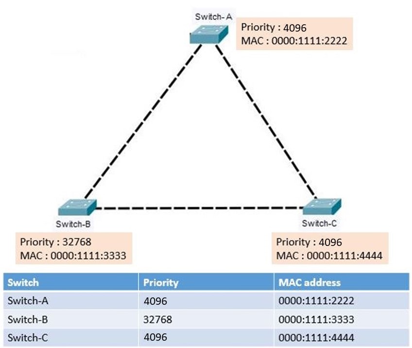 Look at the above topology, where Switch A, Switch B, and Switch C exchange BPDU frames with each other to elect the root bridge. The switch having the lowest bridge id becomes the root bridge.
- To determine the root bridge, the switch having the lowest bridge ID is selected.
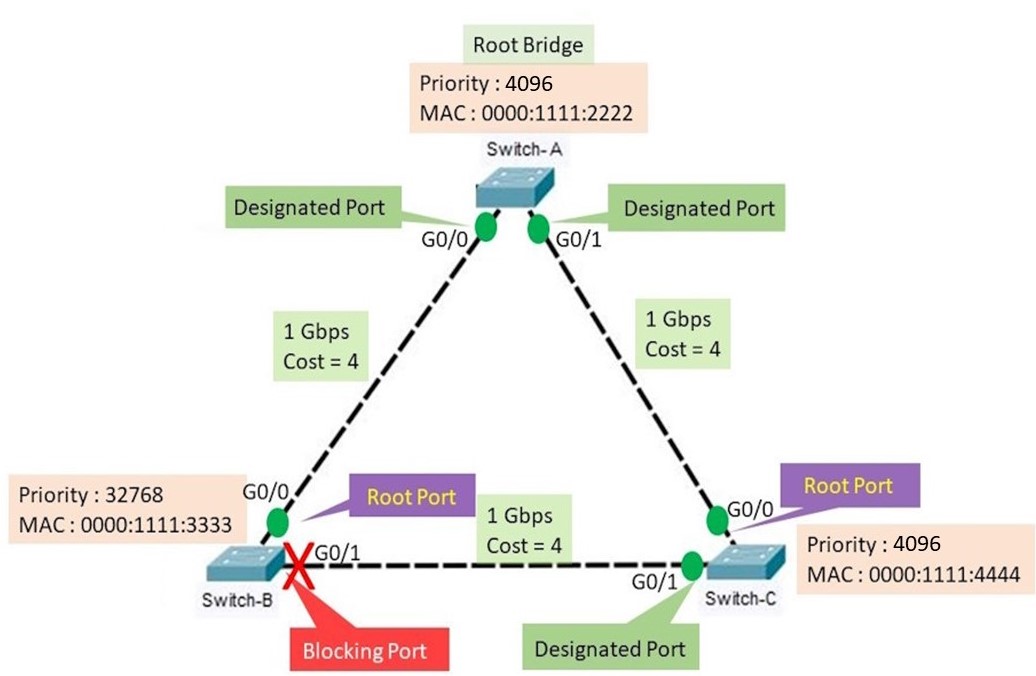
- The priority value of Switch A and Switch B is 4096.
- The priority value of Switch B is 32768.
- Since Switch A and C have the lowest but similar values, the mac address is considered for the tie-breaker.
- In this case, Switch A has the lowest MAC value, hence Switch A becomes the root bridge.
Step 2: Identifying the root port
During the process of STP convergence, the roles of the switch are significant as they are assigned different port roles.
The different types of port roles are root ports, designated ports, non-designated ports, and disabled/blocking ports.
Root port
The root exists only on non-root bridges It provides the best path having the lowest cost to reach the root bridge. Only one root port is allowed to be the root port in a non-root switch.
Designated Port
The designated port is available in both the root bridge and the non-root bridge.
In the root bridge- all ports are the designated ports.
In non-root bridges- Only one port that receives and forwards the frames to the root bridge is the designated port.
There will be only one designated port per segment. In case of multiple switch environments in a segment, there will be the election process of the designated port.
Non-designated Port
The non-designated port is also called the blocking port. The non-designated port is a port on abridge that has not been selected to forward frames on a particular LAN. It may still be forwarding frames as part of the STP tree.
Disabled/Blocking Prot
A blocking port does not participate in the spanning tree process. It is in an administrative shutdown state. It does not forward or receive frames and is used to prevent loops.
- The second step in the process of STP convergence is the identification of the root port.
- To become the root port, the switch must have the lowest root path cost.
- The switch can have only one root port in a non-root switch.
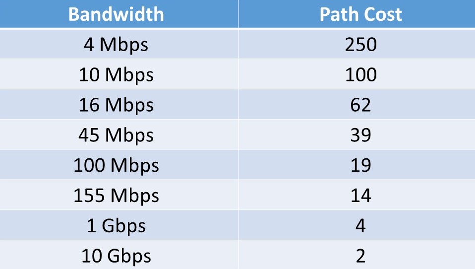
- Path cost is the cumulative cost to the root bridge based on the bandwidth of the link. The higher is the bandwidth, the lower will be the root cost.
- The following table shows the bandwidth and its corresponding path cost value.
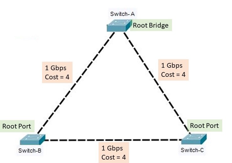
- In the above topology, The switches are connected with each other by a 1 Gbps link having a path cost of 4.
- Switch A has a cumulative path cost of 0 since it is the root bridge.
- When switch A sends out the BPDU message to the neighboring switch, it advertises the path cost of 0.
- Switch B has two paths to reach the root bridge. One is a directly connected link having a path cost of 4 and the other one is through a switch whose cumulative path cost will be 4+4 =8.
- The lowest cumulative path is considered to be the superior.
- For switch B the directly connected port to switch A will be the root port.
- similarly, Switch C is directly connected to Switch A with a path cost of 4. Hence, the directly connected port to the root switch will be the root port for switch C.
Step 3: Identifying the designed port
 The third and final step in STP convergence is the identification of the designated port.
- A single designated port must be identified for each network segment.
- The designated port is responsible for forwarding BPDU configuration frames generated by the root bridge to that segment.
- Since Switch-A is elected as the root bridge, hence all the ports of Switch-A will be identified as the designated ports.
- The Switch-A starts sending the BPDU configuration frame generated by the root bridge through its designated port with a cost to reach the root bridge as 0.
- The Switch-B receives the BPDU frame at its G0/0 port which is directly connected to the root bridge Swithc-A.
- The Switch-C also receives the BPDU configuration frame at its G0/0 port which is directly connected to the root bridge.
- Further, Switch B and Switch C exchange the received BPDU frame among themselves.
- Both switches B and C check the path cost of the BPDU frame.
- Since switches B and C are connected with a 1Gbps link, the path cost of both of them is 4.
- Further to decide which switch will have the designated port, there will be a tie-breaker between them.
- The Switch port with the lowest bridge ID will decide to be the designated port.
- In this case, Switch C has the lowest bridge ID compared to the switch, hence port G0/1 of the switch will be elected as the designated port.
- The switch B has only one root port and there can be only one root port on the non-root bridge. Thus the port G0/1 of the switch will be elected as the blocking port.
| ← Prev | Next → | |
| Introduction to Spanning Tree Protocol | Different Types of Spanning Tree Protocols |