In this section, we will discuss the CCNA 200-301 exam topic “Introduction to spanning tree protocol”. The spanning tree protocol is a network protocol that runs on the layer 2 device such as ethernet switches and bridges. This topic will focus on what is spanning tree protocol, an overview of STP, the need for STP in layer 2 switching, basic terminologies related to STP.
Introduction to Spanning Tree Protocol
The spanning tree protocol (STP) is implemented in layer 2 devices like switches and bridges. The spanning tree protocol helps to resolve the issues that arise due to the redundant links in a layer 2 network.
Generally, the redundant or backup links are established for the fault-free performance of the data network. The multiple links help to resume the connectivity, even if one link fails.
But the serious disadvantage with the redundant link is that it starts creating switching loops. Such looping cases are intolerable when multiple links started forwarding the data frames simultaneously.
To avoid the switching loop issue at the layer 2 network, the spanning tree protocol(STP) is introduced. The basic purpose of the spanning tree protocol is to allow only one link to forward the frame, whereas blocking all other redundant links. It also restores the redundant link, in case any other link failure.
Overview of Spanning Tree Protocol
- The spanning tree protocol is a layer 2 network management protocol.
- The purpose of implementing STP in the layer 2 device is to address broadcast storms.
- It avoids switching loops that occur due to redundant links.
- It also restores the redundant links, in case of the main link fails.
- STP uses a spanning tree algorithm to detect redundancy and eliminate the switching loops.
- The spanning-tree protocol was first introduced by DEC (Digital Equipments Corporation) in 1985.
- Later on, it has become the open-source standard and defined as IEEE 802.1d standard.
- STP is enabled by default in Cisco Catalyst Switch.
- The working of STP involves series of processes to avoid looping conditions. The process of STP is discussed in detail in the later section.
- Switches share BPDU (Bridge Protocol Data Unit) messages among themselves to discover loops.
Different operating states of a Switch port
- Disable State
- Blocking State
- Listening State
- Learning State
- Forwarding State
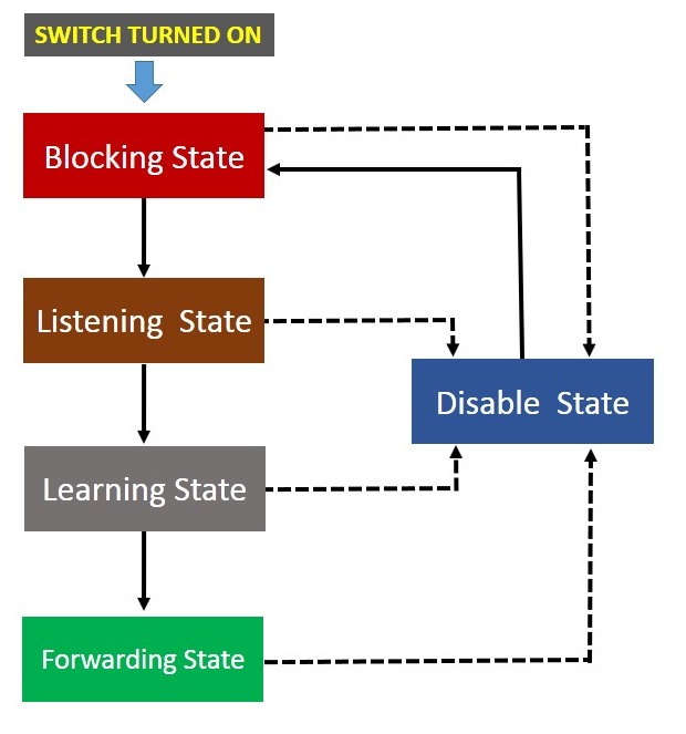
Disable State
The switch port is said to be in disable state when STP operations are disabled on the port. The disabled port does not participate in the process of spanning-tree protocol operation.
Blocking State
When the switch is turned ON, all the switch ports will be in a blocking state initially. It is also considered to be in standby mode. During this state, switch listen to the incoming frame and BPDU. But it only processes the BPDU and learns about network topology. It then determines which port will become the root port or the designated port.
The blocking state lasts for 20 seconds. After that, the root port or the designated port jumps into the next state, most probably the listening state. The remaining port will still remain in the blocking state.
Listening State
The root port or the designated port enters the listening state after 20 seconds of duration in the blocking state. However, all other ports, except the root port still remain in the blocking state.
During the period of listening state, it only receives and proceses the BPDU. Whereas, it discards all other frames recieved fron LAN segment or the other switch port. The switch port remains in the listening for 15 seconds before it enrers into the learning state.
Learning State
The switch port enters into the learning state after 15 seconds of listening state. During the learning state, it receives and processes BPDU. It also receives the frame and update the mac table data base, but does not forward the frame to the exit interface. The duration of learning state is 15 seconds. After that, it enters into the forwarding state.
Forwarding state
The forwarding state of the switch port is the normal mode. During the forwarding state, it receives frames and BPDU. It then processes them, update the mac table and forward the frames to their respective destination.
Some Important STP Terminologies
Root Bridge
- The first important term you need to know for understanding STP operation is the root bridge.
- The switch having the lowest Bridge Id is elected as the root bridge.
- The root bridge is the focal point of network amd is placed at the top of the logical topology of the network tree.
- The value of bridge ID will decide which switch will activate the root bridge in a topology.
- The switch with lowest Bridge ID is elected as the root bridge.
- The bridge ID is a 8 byte unique number assigned to the each switch in a network.
- By Default, all the Cisco switches have the priority number 32768.
- If the priority ID is same for all the switch, the selection of root bridge is on the basis of lower value of mac address
- The selection of root bridge occurs every time the topology changes. The topology change occurs when new switches are added, old switches are removed or turned off.
- If the BPDU are not sent from root bridge to the other switch within 20 seconds, the other switch assume that the root bridge stops working. Then, there is a reselection of root bridge among the other switch.
Non-root Bridge
There is only one root bridge in a single network segment. All other switches are then said to be non root bridge, excluding the root bridge.
The non bridge periodically update their STP database, after receiving BPDU from the root bridge.
Root Port
In Spanning Tree Protocol (STP), the root port is the port on a non-root bridge that provides the shortest path to the root bridge in the network topology. The root port is responsible for forwarding all traffic sent from non-root bridges towards the root bridge to ensure a loop-free network. If multiple ports provide the same shortest path to the root bridge, the bridge selects the port with the lowest port ID as the root port.d
Designated Port
In Spanning Tree Protocol (STP), designated ports are the ports on each non-root bridge that are closest to the root bridge for each segment. These ports are responsible for forwarding traffic towards the root bridge and preventing loops in the network.
Non-designated Port
Non-designated ports are the ports on each non-root bridge that are not designated as the root port or the designated port. These ports are usually blocked to avoid forwarding of traffic that can create loops in the network. They only monitor incoming and outgoing BPDUs but do not forward any frames, and they are available to become designated ports if the designated port on the same segment fails or transitions to a blocking state due to a topology change.
How Spanning Tree Protocol works
Now, let us understand how STP. The entire process of STP operation completes in three distinct steps.
- Selection of the root bridge
- Selection of the root port
- selection of the designated ports and non designated ports
Designated ports are also called forwarding ports, and non-designated ports are called blocking ports.
The working of spanning tree protocol is explained in details with examples in the next section. Kindly refer to the following article about How STP works.
How Spanning Tree Protocol Works
| ← Prev | Next → | |
| Configure and Verify Layer 2 Discovery Protocol (CDP & LLDP) | How Spanning Tree Protocol works |