The original Spanning Tree Protocol stopped networks from crashing, but it was incredibly slow to fix itself when a cable broke. Rapid PVST+ fixes this problem by repairing broken network paths in less than a second while letting you control traffic for each individual group of users.
This article breaks down exactly how Rapid PVST+ works, including its different port jobs, how it switches states instantly, and the safety tools used to protect your network.
What is Rapid PVST+
Rapid PVST+ stands for Rapid Per-VLAN Spanning Tree Plus. It is a network protocol used on Cisco switches to prevent broadcast storms and network crashes caused by redundant data loops while ensuring your network recovers instantly if a cable fails.
It is Cisco’s enhancement to IEEE 802.1w (Rapid STP). It provides a separate spanning tree instance for every single VLAN, allowing for optimal traffic engineering and lightning-fast convergence times (usually under a second, compared to the traditional 30–50 seconds).
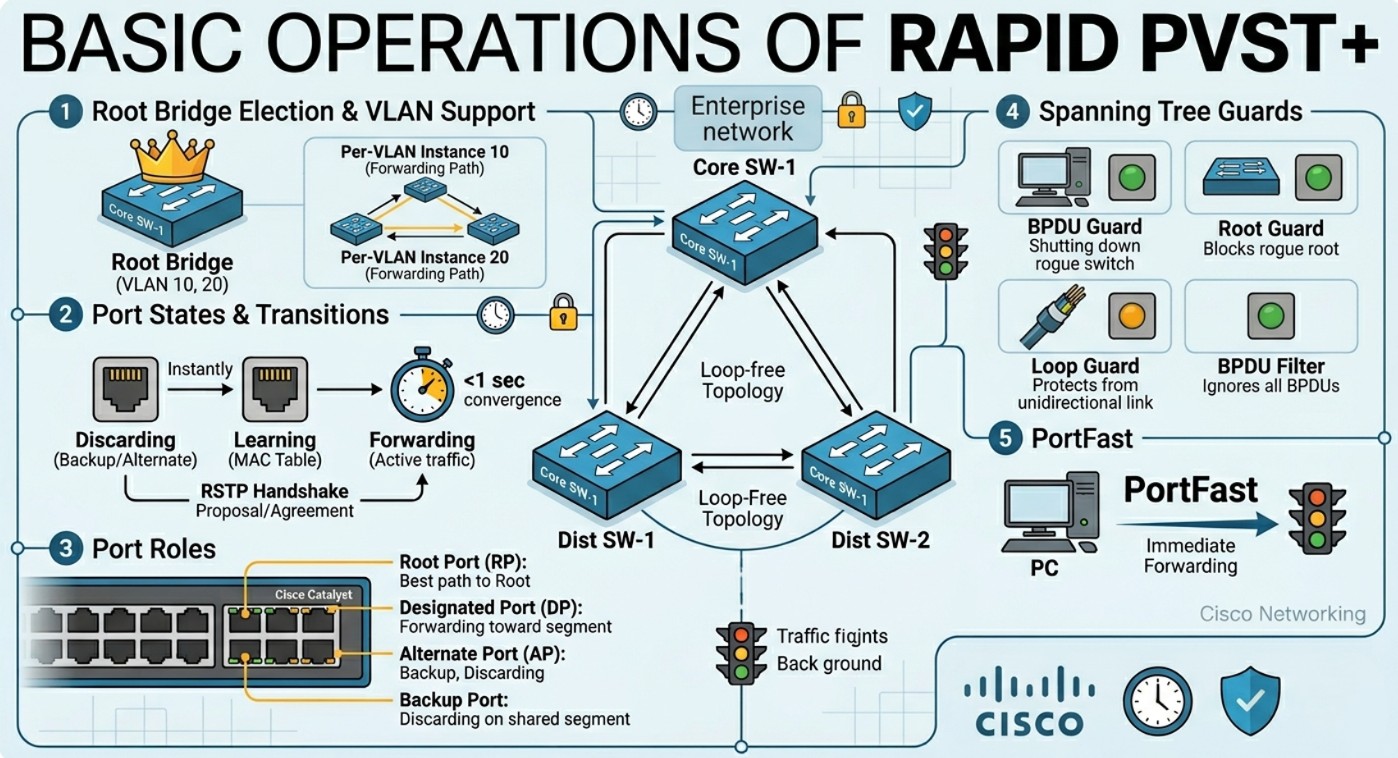
BAsic Operations of Rapid PVST+
At its core, Rapid PVST+ keeps a network stable by dynamically mapping out the best paths between switches, blocking redundant links to prevent data loops, and instantly opening those backup links if a primary connection fails.
Here is how a Rapid PVST+ network builds and maintains its loop-free topology during basic operations.
1. Electing the “Boss” (The Root Bridge)
When switches running Rapid PVST+ are powered on, they don’t know the layout of the network. They immediately begin broadcasting messages called BPDUs (Bridge Protocol Data Units) to find out who should control the network map.
- Every switch has a unique ID called a Bridge ID (BID), which is a combination of a priority number and its MAC address.
- The switches play a game of “lowest number wins.” The switch with the lowest Bridge ID is elected as the Root Bridge.
- Every single path calculation in the network is measured by how close or far it is from this master Root Bridge.
Root Bridge (Primary / Secondary)
- Primary Root Bridge: The switch manually configured to have the lowest priority (usually
24576), forcing it to win the election. - Secondary Root Bridge: A backup switch configured with a slightly higher priority than the primary (usually
28672). If the primary fails, the secondary seamlessly takes over.
2. Setting Up the Highway (The Proposal/Agreement Handshake)
Unlike traditional spanning tree, which relies on slow, passive timers (waiting 15 seconds to listen, then 15 seconds to learn), Rapid PVST+ uses an active, aggressive Proposal and Agreement handshake to set up its ports in milliseconds.
- The Proposal: A switch port sends a handshake message (Proposal) down a link, saying, “I want to be the main forwarding path (Designated Port) for this segment.”
- The Sync: The receiving switch temporarily blocks its other ports to prevent any accidental loops while it processes the request.
- The Agreement: Once the receiving switch verifies this is the fastest path back to the Root Bridge, it sends an Agreement back.
- Both ports instantly transition to the Forwarding state. This entire handshake takes place in a fraction of a second.
3. Assigning the Port Roles
Once the Root Bridge is elected, individual ports are assigned specific roles:
- Root Port (RP): The single port on a non-root switch that has the lowest “root path cost” (the best physical route back to the Root Bridge). Every non-root switch must have exactly one Root Port.
- Designated Port (DP): The port on a network segment (link) that is responsible for forwarding traffic and sending Bridge Protocol Data Units (BPDUs) down the line. The Root Bridge only has Designated Ports.
- Alternate Port: A backup port that receives BPDUs from another switch but is kept in a discarding state. If the Root Port drops, the Alternate Port can instantly transition to take its place.
- Backup Port: A redundant port connected to the same shared segment (hub) as another designated port on that switch. It is rarely seen in modern switched networks.
4. Continuous Monitoring and Instant Healing
Once the network is up and running, the Root Bridge sends out “heartbeat” BPDU messages every 2 seconds.
If a cable is unplugged or a switch fails, the downstream switches notice the missing heartbeats within just 6 seconds (3 missing BPDUs). Because the backup Alternate Ports have already calculated the next-best route in advance, they instantly unblock and start forwarding traffic, ensuring the network heals itself with near-zero downtime.
Port States (Forwarding / Blocking)
Traditional STP has five port states. Rapid PVST+ simplifies this down to just three functional states, eliminating the slow Listening and Learning delays for standard topologies.
| RSTP/Rapid PVST+ State | Operational Status | Transmits Data? | Learns MACs? | Equivalent Traditional STP State |
| Discarding | Active | No | No | Disabled, Blocking, Listening |
| Learning | Transitional | No | Yes | Learning |
| Forwarding | Active | Yes | Yes |
Instead of relying on rigid timers to move from Discarding to Forwarding, Rapid PVST+ uses an active Proposal/Agreement handshake mechanism between switches to rapidly transition ports to Forwarding in milliseconds.
PortFast
By default, any switchport that changes link status must go through the Spanning Tree calculation process. If you plug a PC or a server into a standard switchport, it could take up to 30 seconds to get an IP address via DHCP because the port is waiting on STP.
PortFast bypasses this delay.
- It immediately transitions an access port into the Forwarding state the moment it detects a link.
- Crucial Rule: PortFast should only be configured on edge ports connected to end-user devices (PCs, printers, IP phones). Enabling it on a port connected to another switch can cause immediate, catastrophic network loops.
RSTP ToolsetGuard
The RSTP Toolset (also widely referred to as the STP Toolkit) is a collection of optional security and stability features configured on network switches. While Rapid PVST+ and RSTP prevent data loops by default, they can still be vulnerable to human error, rogue equipment, or physical cable faults.
This toolset acts like an advanced security system to shield, lock down, and stabilize your Spanning Tree topology.
BPDU Guard
- What it does: Automatically shuts down a port if it receives a BPDU.
- Best Practice: Use this in tandem with PortFast on edge ports. If a user accidentally plugs a rogue switch into a PortFast-enabled wall jack, BPDU Guard detects the switch’s BPDUs and puts the port into an
err-disablestate, stopping a potential loop before it starts.
BPDU Filter
- What it does: Effectively disables Spanning Tree on the port by stopping it from sending or processing received BPDUs.
- Best Practice: Use with extreme caution. It is typically used in service provider environments or niche testing labs where you explicitly want to ignore STP behavior on a specific link.
Root Guard
- What it does: Prevents an unauthorized, newly introduced switch from tricking the network and electing itself as the Root Bridge.
- How it works: If a port configured with Root Guard receives a superior BPDU (a lower Bridge ID than the current Root), it immediately places that port into a root-inconsistent (effectively discarding) state. No traffic passes until the rogue switch stops advertising its superior priority.
- Best Practice: Configure this on ports facing external networks or downstream access switches that should never become the core of your network.
Loop Guard
- What it does: Protects the network from loops caused by unidirectional link failures (e.g., a fiber optic cable where the Rx strand works but the Tx strand fails).
- How it works: An Alternate or Root port expects to constantly receive BPDUs from its neighbor. If BPDUs suddenly stop arriving due to a hardware failure, standard STP would eventually assume the link is dead and transition the port to Forwarding—creating a massive loop. Loop Guard recognizes this silence and instead drops the port into a loop-inconsistent state.
Definitely consider that which you stated. Your favourite justification seemed to be at the internet the easiest
thing to take into accout of. I say to you, I
certainly get irked whilst other people think about concerns that they
just do not recognize about. You controlled to hit the nail upon the highest and also
defined out the entire thing without having side-effects , other people could take a signal.
Will probably be back to get more. Thanks