In modern networking, the physical interfaces and cabling types play a crucial role in designing efficient networks. This section will cover different types of physical interfaces and cabling like Copper and Fiber optic cables, single-mode and multimode fiber, Ethernet shared media and point-to-point connections.
Introduction
Physical interfaces and cabling types work together to enable network communication, but they are not the same thing.
A physical interface is the actual port on a device (like an Ethernet or fiber port) that connects it to the network and operates at Layer 1 of the OSI Model. Whereas cabling types refer to the medium used to transmit data between those interfaces. The interface is the entity where you connect the cable, and the cable is the physical media that carries the data. Both of them must be compatible with each other to ensure proper data transfer.
For example, an Ethernet interface typically uses copper cables like Cat5e or Cat6 for short-distance communication, whereas fiber interfaces use single-mode or multimode fiber cables for high-speed and long-distance links.
Physical Interfaces
Physical interfaces are the actual hardware connections that allow network devices (like routers, switches, and PCs) to communicate with each other. These interfaces define how data physically travels from one device to another, through cables, connectors, and ports.
Types of Physical Interfaces
The most common physical interfaces used in modern day networks are:
- Ethernet Interfaces (Copper-based): These are the most common interfaces used in LAN networks.
- Fiber Optic Interfaces: They are used for high-speed and long-distance communication.
Ethernet Interfaces
Ethernet interfaces operate according to standards defined by the Institute of Electrical and Electronics Engineers, specifically the IEEE 802.3 family of protocols. These standards define aspects such as data transmission speeds, cable types, signaling methods, and frame formats.
Each Ethernet interface is assigned a unique MAC (Media Access Control) address, which is used to identify the device on a local network.
Modern Ethernet interfaces support a range of speeds, including 10 Mbps (Ethernet), 100 Mbps (Fast Ethernet), 1 Gbps (Gigabit Ethernet), 10 Gbps, and even higher in enterprise environments. The most common connector used is the RJ-45 port, which connects to twisted-pair cables like Cat5e, Cat6, or Cat7.
Ethernet interfaces can operate in different modes:
- Half-duplex: Data can be transmitted in both directions, but not at the same time.
- Full-duplex: Data can be transmitted and received simultaneously, improving performance.
They also support features such as auto-negotiation, where connected devices automatically select the best speed and duplex mode, and flow control to manage data transmission and prevent packet loss.
Ethernet interfaces are represented by logical names (like eth0, en0, or Ethernet0) in operating systems. Network administrators configure these interfaces with IP addresses, subnet masks, and other parameters to enable communication across networks.
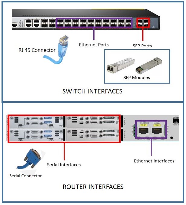
Fiber Optic Interfaces
Fiber optic interfaces are network interfaces that use light signals instead of electrical signals to transmit data through fiber optic cables, making them ideal for high-speed and long-distance communication. These interfaces also operates at Layer 1 of the OSI Model and are commonly found in switches, routers, and data center equipment.
They use specialized transceivers like SFP (Small Form-factor Pluggable), SFP+, QSFP, etc., to connect with fiber cables.
There are two main types of fiber used with these interfaces.
- Single-mode fiber (SMF) uses a very thin core and laser light to transmit data over long distances (up to tens or even hundreds of kilometers), making it suitable for WANs and ISP backbones.
- Multimode fiber (MMF) has a thicker core and uses LED light, which supports shorter distances (typically up to a few hundred meters) and is commonly used inside buildings or campuses.
Fiber optic interfaces are also categorized based on standards such as 1000BASE-SX, 1000BASE-LX, 10GBASE-SR, and 10GBASE-LR, where “SR/SX” indicates short-range (usually multimode) and “LR/LX” indicates long-range (usually single-mode).
These interfaces provide very high bandwidth, low latency, immunity to electromagnetic interference (EMI), and better security compared to copper interfaces.
Fiber Connectors
Fiber connectors are devices used to join optical fibers so that light signals can pass from one fiber to another with minimal loss.
There are different types of fiber connectors, such as SC, LC, ST, and FC, which vary based on their size, design, and locking mechanism.
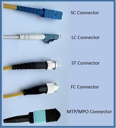
- SC (Subscriber Connector): SC connector is a square-shaped fiber connector that uses a push-pull mechanism and is widely used in telecom and broadband networks.
- LC (Lucent Connector): LC connector is a small-sized fiber connector with a latch mechanism, commonly used in high-density applications like data centers.
- ST (Straight Tip Connector): ST connector is a round fiber connector that uses a twist-lock mechanism and is mainly found in older or legacy networks.
- FC (Ferrule Connector): FC connector is a screw-type fiber connector that provides a strong and stable connection, often used in precision and testing equipment.
- MTP/MPO (Multi-Fiber Push-On): MTP/MPO connector is a multi-fiber connector that can connect multiple fibers at once and is used in high-speed data transmission systems.
Different Physical Interfaces defined by IEEE 802.3 Standards
The following table compares the different physical interfaces defined by IEEE 802.3 standards with different speeds from 10 Mbps to 100 Gbps, along with the cable type and distance.
| IEEE Standard | Ethernet Type | Speed | Cable Type | Max Distance | Common Examples |
| 802.3 | Ethernet | 10 Mbps | Coaxial / Cat3 | 100 m (UTP), 500 m (coax) | 10BASE-T, 10BASE5 |
| 802.3u | Fast Ethernet | 100 Mbps | Cat5 / Fiber | 100 m (TX), 2 km (FX) | 100BASE-TX, 100BASE-FX |
| 802.3ab | Gigabit (Copper) | 1 Gbps | Cat5e/Cat6 | 100 m | 1000BASE-T |
| 802.3z | Gigabit (Fiber | 1 Gbps | Fiber (MMF/SMF) | 550 m – 10 km | 10GBASE-SR, LR, ER |
| 802.3ae | 10 Gigabit | 10 Gbps | Fiber / Copper | 300 m – 40 km | 10GBASE-SR, LR, ER |
| 802.3an | 10G (Copper) | 10 Gbps | Cat6a/Cat7 | 100 m | 10GBASE-T |
| 802.3ba | | 40G/100G | 40–100 Gbps | Fiber | Up to 100 km | 40GBASE-SR4, 100GBASE-LR4 |
Ethernet Interface Naming Conventions
Ethernet cable naming conventions follow a structured pattern defined by the IEEE. These names describe speed, signaling method and physical medium.
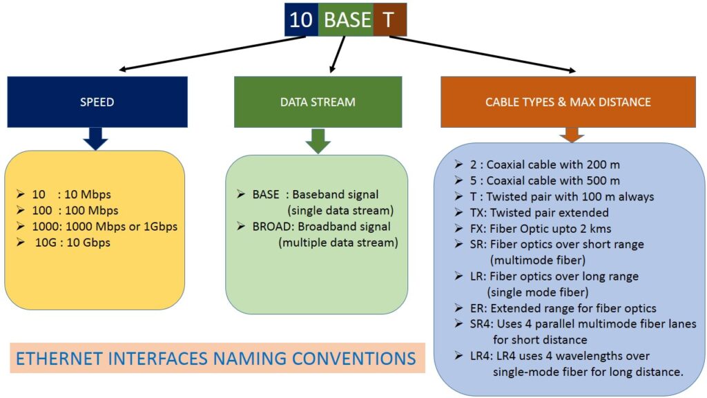
The standard Ethernet Interface Name contains three different parts.
The first Part indicates the data transfer rate in Mbps.
- 10 : 10 Mbps
- 100 : 100 Mbps
- 1000 : 1000 Mbps
- 10G : 10 Gbps
The middle part indicates the signaling type.
- Base : Baseband signal (the signal is sent in its original digital form using the full bandwidth of the cable
- Broad : Broadband signal (multiple signals to be sent simultaneously over the same communication medium by dividing the bandwidth into separate frequency channels.)
Ethernet uses mainy baseband signalling, while broadband is used in Intenret and cable TV.
The last part indicates the cable types.
- For twisted pair
- T : Twisted pair
- TX : Enhanced Twisted pair
- For fiber optics
- FX : Fiber optics upto 2 kms
- SR : Fiber optics over shoirt range (multimode fiber)
- LR : Fiber optics over long rnage (singlemode fiber)
- ER : Extended range for fiber optics
- SR4 : 4 parallel multimode fiber lanes for short distance
- LR4 : LR4 uses 4 wavelengths fro long distance
Physical Cabling Types
Physical Cabling Types are the actual physical medium used to connect networking devices and carry data signals from one device to another.
There are mainly aminly three types of physical cables are used in networking.
- Twisted Pair Cable
- Coaxial Cable
- Fiber Optics Cable
Let us understand them one ny one.
Twisted Pair Cable
A Twisted Pair Cable is one of the most widely used transmission media in networking and telecommunications. It consists of multiple pairs of insulated copper wires, where each pair is tightly twisted together to reduce electromagnetic interference and crosstalk.
Typically, an Ethernet cable contains four such pairs, each color-coded for identification. These twisted pairs are enclosed within an outer protective jacket made of plastic, and in some cases, additional shielding is added (as in shielded twisted pair) to further protect against external noise. The ends of the cable are terminated with connectors like the RJ45 connector, allowing it to be plugged into networking devices such as routers and switches.
Categories of Twisted Pair Cable
- Cat1: Used only for telephone communication and not suitable for data networks.
- Cat2: Supports data speeds up to 4 Mbps and was used in early networking systems.
- Cat3: Supports up to 10 Mbps and was commonly used in older Ethernet and telephone lines.
- Cat4: Supports up to 16 Mbps and was used in token ring networks but is now obsolete.
- Cat5: Supports up to 100 Mbps and was widely used before being replaced by newer cables.
- Cat5e: Supports up to 1 Gbps with reduced interference and is widely used today.
- Cat6: Supports up to 10 Gbps over short distances with improved performance and insulation.
- Cat6a: Supports 10 Gbps over longer distances with better shielding and less crosstalk.
- Cat7: Provides high-speed data transmission with advanced shielding for minimal interference.
- Cat8: Supports 25–40 Gbps speeds and is mainly used in high-performance data centers.
Types of Twisted Pair Cable
- UTP (Unshielded Twisted Pair) : UTP is the most commonly used type of twisted-pair cable in Ethernet LAN. It consists of pairs of copper wires twisted together without any additional shielding, making it lightweight, flexible, and cost-effective for everyday networking. It is widely used in homes and offices and works with standard Ethernet port, but is more susceptible to electromagnetic interference compared to shielded cables.
- STP (Shielded Twisted Pair): STP includes an extra layer of shielding made of foil or braided metal around each pair or the entire cable. The extra shielding helps to protect against electromagnetic interference and crosstalk. It is used in such environment where hihger noise and elecrical interferance persisirt. It is more expensive, thicker, and harder to install than UTP.
- FTP (Foiled Twisted Pair): FTP is a variation where all the twisted pairs are wrapped together in a single metallic foil shield, offering better protection than UTP but less than fully shielded STP, and is often used in environments where moderate interference protection is required without the added complexity of full shielding.
Coaxial Cable
A Coaxial Cable is a type of transmission medium used to carry electrical signals with high efficiency and low interference. It is made up of an inner conductor mostly copper that carries the signal, a dielectric insulator that separates and supports the conductor, an outer metallic shield that protects against interference, and an outer plastic jacket that provides physical protection.
Types of Coaxial Cable
- ·Thick Coaxial Cable (Thicknet): Thick coaxial cable is a heavy and rigid type with a thicker central conductor and insulation, which allows it to carry signals over longer distances with less signal loss.It was commonly used in early Ethernet networks (10Base5) but is now mostly obsolete due to its cost and difficulty of installation.
- Thin Coaxial Cable (Thinnet): Thin coaxial cable is lighter, more flexible, and easier to install compared to thick coaxial cable, making it suitable for shorter-distance communication. It was widely used in early Ethernet networks (10Base2) before being replaced by twisted-pair cables.
- RG-6 Coaxial Cable: RG-6 is a widely used modern coaxial cable with better insulation and shielding. It provides high bandwidth and has low signal loss, making it ideal for cable TV, satellite connections, and broadband internet.
- RG-59 Coaxial Cable: RG-59 is a thinner coaxial cable with lower bandwidth and higher signal loss compared to RG-6. It is commonly used for short-distance applications such as CCTV camera systems.
Fiber Optics Cable
Fiber optic cable is a communication cable that carries information in the form of light signals instead of electrical signals. It is widely used in modern telecommunication systems because it can transmit data at very high speeds over long distances with very low signal loss.
A fiber optic cable is made of extremely thin strands of glass or plastic called optical fibers that carries data in the form of light signals instead of electrical signals. Each optical fiber has two parts :
- The innermost central part is called core through which signal passes in the form of light.
- The core is surrounded by a lower refractive index material called cladding layer that reflects light back into the core using the principle of total internal reflection.
Outside the cladding is a buffer coating that protects the fiber from damage, and all fibers are bundled together within a strength member (like Kevlar) and an outer jacket for mechanical protection against bending, moisture, and external damage.
Types of fiber Optics cables
Fiber optic cables are mainly classified into two types based on how light travels through the core.
Single Mode Fiber (SMF)
Single mode fiber is an optical fiber with a very small core diameter (typically about 8–10 micrometers) that allows only one mode or path of light to propagate through it. This reduces signal distortion and enables efficient data transmission over long distances.
Single mode fiber has very low attenuation (signal loss) and very high bandwidth. It supports transmission over distances of several kilometers without the need for frequent signal amplification. It typically uses laser light sources instead of LEDs for precise signal transmission.
Multi Mode Fiber (MMF)
Multimode fiber has a larger core (around 50–62.5 microns) that allows multiple light rays or modes to travel simultaneously.
Multimode fiber has higher signal attenuation and dispersion compared to single mode fiber. It uses light sources such as LEDs or VCSELs (Vertical Cavity Surface Emitting Lasers). It is suitable for shorter distances, typically up to a few hundred meters to a few kilometers.
Optical fibers are further classified based on how the refractive index changes inside the core.
- Step Index Fiber
- Graded Index Fiber
In Step index fiber, the refractive index of the core is uniform throughout, and it suddenly decreases near the boundary between the core and the cladding. Because of this sharp change (or “step”), light rays travel in a zigzag path by repeatedly reflecting at the core–cladding interface, thius by increasing leads modal dispersion (spreading of the signal) Hence, It is less efficient for high-speed communication over long distances. It is simple in design and can be used in basic or short-distance applications.
In graded index fiber, the refractive index of the core gradually decreases from the center towards the outer edge. This gradual variation causes light rays to bend smoothly instead of sharply reflecting. The light rays traveling farther from the center move faster, which helps them reach the end nearly at the same time as those taking shorter paths. This reduces modal dispersion significantly and improves signal quality.
Connections: Ethernet Shared Media and Point-to-Point
In networking, connections describe how devices communicate over a transmission medium. The two main types are shared media and point-to-point connections.
Ethernet Shared Media
Ethernet shared media is a network setup in which multiple devices use the same communication channel (or medium) to send and receive data. This means all devices share the same bandwidth, and only one device can successfully transmit at a time to avoid data collisions. In Traditional Ethernet networks using hubs or early bus topologies, collision may occur if two devices tried to data simultaneously. As a result, channel bandwidth are shared and congestion may occur.
To avoid this critical issue, a method called Carrier Sense Multiple Access with Collision Detection (CSMA/CD) is used by these shared media network. In this method, each device first listens to the network to check if it is free before transmitting. If a collision happens, the devices stop, wait for a random time, and then try again.
Shared media Ethernet was commonly used in older network designs like bus topology and hub-based networks. However, it had limitations such as lower performance, higher chances of collisions, and reduced efficiency as more devices were added.
Modern Ethernet networks mostly use switches instead of hubs, creating dedicated connections for each device. This eliminates collisions and improves overall speed and reliability, so shared media Ethernet is now largely obsolete.
Point-to-Point Connection
In a point-to-point connection, there is a dedicated communication link between exactly two devices, allowing direct and uninterrupted data transfer. Each connection has its own separate channel, so there are no collisions and full bandwidth is available for communication between the two endpoints. Modern Ethernet networks using switches operate on this principle, where each device gets a dedicated link to the switch, improving speed, efficiency, and security.
Point-to-point connections can be established using different media such as twisted pair cables, fiber optic cables, or wireless links. Modern Ethernet networks using switches are good examples of point-to-point connections, where each device has its own dedicated link to the switch.
The main advantages of point-to-point connections include high speed, better security, low latency, and no collisions. However, they may require more cables and infrastructure compared to shared networks, which can increase cost in large setups.