This section will explain how to configure and verify VLANs spanning multiple switches with an example. We are using the Cisco managed switch to illustrate how to configure VLAN using Cisco packet Tracer simulator software for illustration. Catalyst Switch (2950T) is used for practical purposes in Packet tracer to configure VLANs.
To understand the basics of VLANs and its Types, kindly refer to the following articles
What is Virtual LAN and its Types
Configure and Verify VLANs
As we know, VLAN is a process of breaking down a single broadcast domain into multiple broadcast domains. Thus, VLAN helps to segment a single large network into a number of smaller networks. In this way, the implementation of VLAN makes the network management and administration easier, better control over the unwanted traffic flooding across the switch ports, and enhances the security policies.
Let us understand the topic in-depth with the following illustration.
Suppose, you are working in an organization as a network administrator. Your organization has three different departments: ACCOUNTS Department, HR Department, and Inventory Department. The computers of all the departments are connected with a single LAN. As more computers will be going to add to the network in the near future. Due to which the network performance might affect badly. The problem can be solved by assigning separate VLANs to the respective departments.
So, the infrastructure management asked to solve the issue by implementing VLAN so that each department is connected with separate VLAN. Doing this, you can control the unwanted traffic flow to different VLAN as well as your network security will also be enhanced.
Configuration of Virtual LAN in Switch
To implement, you have to follow the steps below.
Step1: Create VLAN
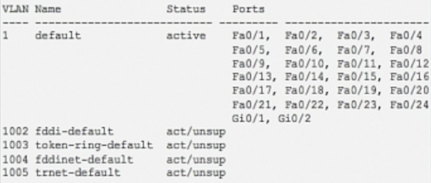
The first step for configuring VLAN on a managed switch is to create a VLAN ID. Different VLANs on the network are identified by their VLAN IDs. The VLAN ID is a numerical number that ranges from 1 to 4094. The VLAN 1 is called default VLAN. The default VLAN 1 always exists on every switch even if it is not configured for VLAN. So, VLAN 1 cannot be assigned to any other VLANs. Apart from this, VLAN ID 1002 to 1005 is reserved for Token Ring and FDDI network. You can use VLAN ID 2 to 1001 and from 1006 to 4094. VLAN ID 2 -1001 are called normal range VLANs and are used for the small and medium-sized enterprise network. VLAN ID 1006 – 4094 are called extended-range VLANs and are used for large enterprise networks and service providers where very large numbers of customers are connected.
| Switch(config)#VLAN <VLAN ID>
Switch(config)#NAME <VLAN NAME> |
Step 2: Assign access Ports to respective VLANs
After VLAN is created, the next step is to assign switch ports to respective VLANs. There are two types of ports: access ports and trunk ports. The access port is used to connect the switch to the device in a single VLAN. Whereas the trunk port is assigned to the trunk link. The access ports connect the device having the same VLAN membership. The access port that is assigned VLAN membership is configured separated one by one entering the interface mode. Else, if more than one port is to be configured for VLAN membership, range command is used to configure them all in a single line command.
When a single interface is selected, then the following command is executed.
|
Switch(config)#interface <access port ID> Switch(config-if)# switchport mode access Switch(config-if)#switchport access VLAN <VLAN ID>
|
When multiple ports are selected, then the following command is executed.
| Switch(config)#interface range <first port ID> – <last port ID> Switch(config-if)# switchport mode accessSwitch(config-if)#switchport access VLAN <VLAN ID> |
Step 3: Assign trunk port to a trunk link
The trunk link is established between the managed switches. The trunk port can carry the traffic of different VLANs.However, you can restrict the traffic of specific VLANs by employing Allow or deny command.
| Switch(config)#interface <trunk port id>
Switch(config)#switchport mode trunk |
This command will allow all VLAN traffic to pass through the Trunk link.
Step 4: Configure IP address to VLAN
The network sees VLAN as the logical interface. Hence, it can be configured with an IP address for managing and troubleshooting the switch remotely. The VLAN IP addressing is used to provide inter-VLAN to communicate between the different VLANs.
| Switch(config)#interface VLAN <VLAN ID>
Switch(config-if)#ip address <IP address> <Subnet mask> |
In the example, we are using the Packet Tracer simulator for implementing VLANs to the switch.
| Note! |
| Packet Tracer is a simulation software designed by Cisco Systems. It provides a virtual platform to design network topologies and connect different Cisco devices like router, switches, firewalls, servers, and simulate the configuration of, etc. It almost supports all the configuration commands needed by the routers and switches as if they are working in the real environment. It is very helpful for the network designers, administrators, and students to imitate the commands of real Cisco devices. It is freely downloadable from the Cisco Official website https://www.netacad.com/courses/packet-tracer. |
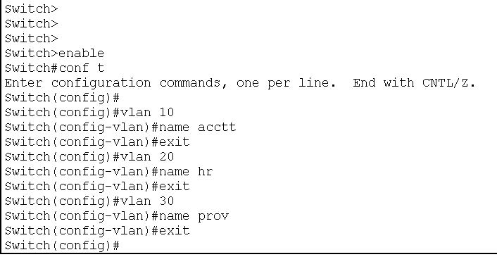
The following VLAN IDs are assigned to the respective branches.
- VLAN 10 for Accounts
- VLAN 20 for HR
- VLAN 30 for Inventory
The Cisco Switch has 24 port FastEthernet ports and the dedicated Gigabit Ethernet ports for the trunk. The ports FastEthernet 0/1 to FastEthernet 0/8 is assigned to VLAN 10 ( Accounts), ports FastEthernet 0/9 to FastEthernet 0/16 is dedicated for VLAN 20 ( HR) and the ports FastEthernet 0/17 to FastEthernet 0/ 24 are for VLAN 30 ( (Inventory). Gigabit Ethernet port 0/1 is used for the trunk link.
- VLAN 10—– FastEthernet 0/1 to FastEthernet 0/8
- VLAN 20 —— FastEthernet 0/9 to FastEthernet 0/16
- VLAN 30 ——- FastEthernet 0/17 to FastEthernet 0/ 24
- Trunk link —— GigabitEthernet 0/1
LAB Setup
Create a topology in packet tracer with given parameters, as shown in the following image.
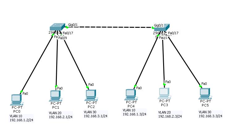 Configuration of VLAN in Managed Switch
| PCs Configuration | |||||
| Device | IP Address | Subnet Mask | Gateway | VLAN | Connected With |
| PC0 | 192.168.1.2 | 255.255.255.0 | 192.168.1.1 | VLAN 10 | Switch1 on F0/1 |
| PC1 | 192.168.2.2 | 255.255.255.0 | 192.168.2.1 | VLAN 20 | Switch1 on F0/9 |
| PC2 | 192.168.3.2 | 255.255.255.0 | 192.168.3.1 | VLAN 30 | Switch1 on F0/17 |
| PC3 | 192.168.1.3 | 255.255.255.0 | 192.168.1.1 | VLAN 10 | Switch 2 on F0/1 |
| PC4 | 192.168.2.3 | 255.255.255.0 | 192.168.2.1 | VLAN 20 | Switch 2 on F0/9 |
| PC5 | 192.168.3.3 | 255.255.255.0 | 192.168.3.1 | VLAN 30 | Switch 2 on F0/17 |
| Switch 1 and Switch 2 Configuration | |||
| Port Connected To | VLAN | Link | Status |
| F0/1 With PC0 | VLAN 10 | Access | OK |
| F0/9With PC1 | VLAN 20 | Access | OK |
| F0/17 with PC2 | VLAN 30 | Access | OK |
| Gig 0/1 with switch 2 | VLAN 10,20,30 | Trunk | OK |
Now, follow the step by step configuration as mentioned below:
Step 1: Create VLAN IDs for respective VLANs and name them.
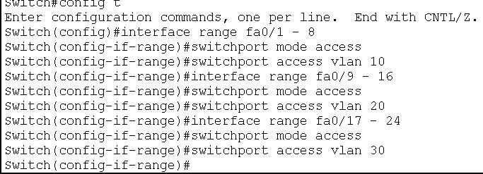
Step 2: Assign access ports to respective VLANs
After creating a VLAN ID, the next job is to assign access ports to respective VLANs. In our case, we will assign fa0/1 to fa0/8 to VLAN 10, fa0/9 to fa0/16 to VLAN 20, and fa0/17 to fa0/24 to VLAN 30.
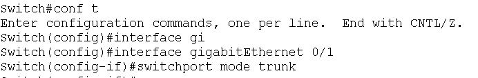
Step 3: Assign switches gigabit port 0/1 to trunk link.
The configuration for switch 1 is complete. Similarly, switch 2 is configured with the same parameters as switch 1
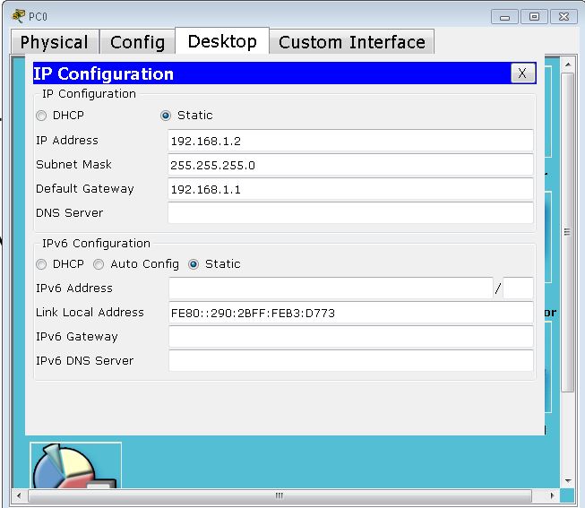
Step 4: Configure IP addresses to the different PCs
To assign IP addresses to the PCs, just double click on PC-PT and Click Desktop menu item and click the IP Configuration. Select Static from radio option and fill IP address, subnet mask, and default gateway IP in given input boxes. Use PC Configuration table to assign correct IP addresses to all the PCs.
Now, Check whether the VLAN is properly configured or not.
For this, launch a ping command from pc0 to other pcs of VLAN.
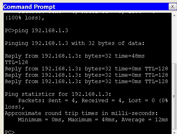
First, ping 192.168.1.3 from 192.168.1.2. Since, both PC belong to the same VLAN, it should communicate with each other. The ping result is as follows :
Next, ping 192.168. 2.3 from 192.168.1.2. Both PCs belong to different VLANs. They should not communicate with each other. The ping result is as follows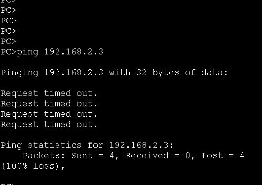
What is Access Port in VLAN
An access port is a switch port that is configured to carry traffic from a single VLAN. Access ports are mostly used to connect end devices such as computers, servers, printers, and IP telephones to a switch.
What is Default VLAN
The Default VLAN, also known as VLAN 1, is a default Virtual Local Area Network (VLAN) created automatically on most switch equipment at the time of installation. By default, all ports on a switch are also members of VLAN 1, which is assigned to all devices on it that have not been manually assigned to another VLAN.
The default VLAN is useful for network administrators for its function of providing connectivity to all devices and ensuring communication between devices that are attached to the switch when other VLANs have not been created. However, it is frequently recommended to create and use a new VLAN other than the default VLAN, because the use of VLAN 1 presents security risks, such as any device attached to the network being able to contact other devices on the same network.
| ←Prev | Next→ | |
| What is Virtual LAN and its Advantages | Configure and Verify Layer 2 Discovery Protocol(CDP and LLDP |